#TIL: Bit-Banging FTDI Breakout
You don’t need Arduino to be able to learn about digital signal.
In the past I’ve been written about electrical engineering as a very valuable skill to be acquired in 2018. The role of electronic gadgets becomes more and more important as they are the “input” and “output” of the future.
Electrical Engineering is just one abstraction below the software. When you’re doing software you generally do not care about signals, voltage, current, analogue or digital. In EE, you need to understand them. My first dive into electronics was typical, I just bought some popular development board and code on it and finally I can write a wifi-connected blinky. Blinky is the ‘hello world’ of electronics.
The problem with that is it’s relatively expensive way of learning about digital signal. Writing code with boards like Arduino, Raspberry Pi, or ESP8266 may still worthwhile however I think I find a cheaper and simpler way by using only your PC and an affordable USB breakout board to learn about digital signal.
The problem with this approach is that the read and write rate is a magnitude slower than using ‘real’ GPIO as we’re actually doing something called bit-bang.
Meet FTDI and libUSB
An FTDI breakout board can be bought for less that $5 nowadays. If you’re working with electronics you usually have this board to do serial communication.
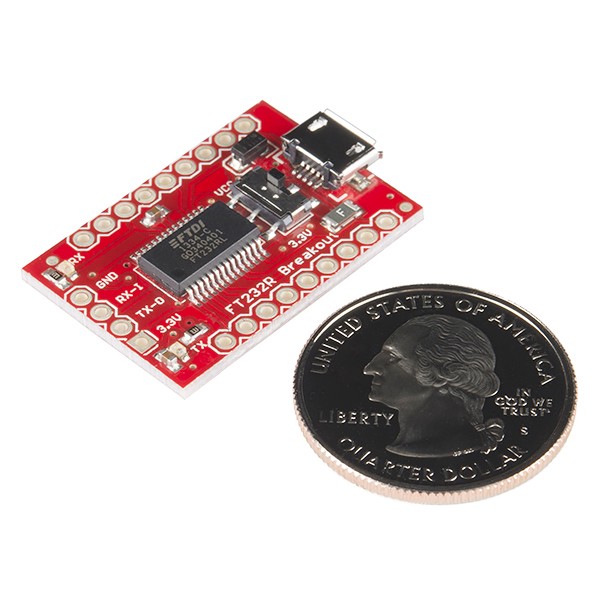
FT232RL Breakout Board
With some cheap basic electronics components we can learn about electronics using your own computer. No cross compiling and flashing required all you need are two libraries: libUSB and libFTDI and your favourite programming language. I assume we’re using macOS or Linux here as they’re easier to work with. As for Windows, you may refer to this StackOverflow Q&A
pylibftdi missing libftdi libusb on Windows install
For Linux you can use apt-get or yum to install libftdi . On macOS, you can use port or brew and of course Xcode. If you’re like me, a macOS user, we need to unload the FTDI driver.
sudo kextunload --bundle-id com.FTDI.driver.FTDIUSBSerialDriver
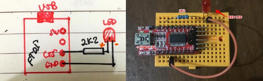
Here’s the simple ‘schematic’ and the photo of the components laid out in the breadboard. plug the USB to your PC to start coding.

Schematic and Breadboard component placement for Blinky
Getting Required Values
I’m using FTDI232R chip, the most common chip used on this breakout. The datasheet says these are the pins and bit number.
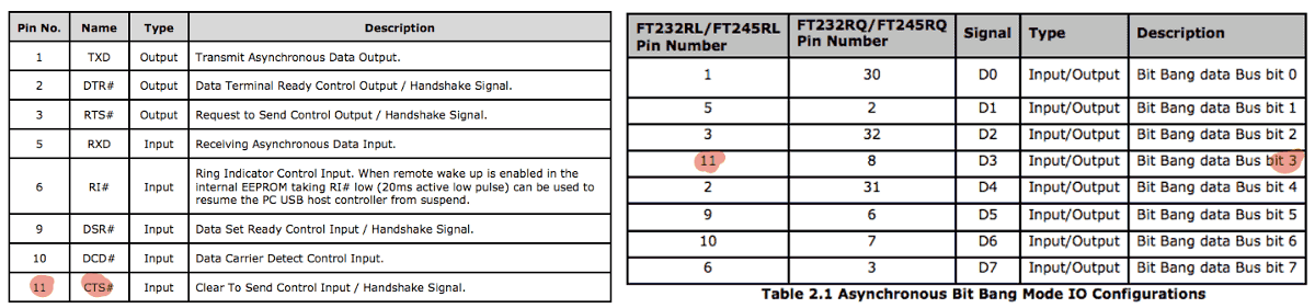
FTDI 232R pin assignment and bit-bang bus.
What we’ll do is called bit-banging which actually we can send and receive raw signal from a pin and control the data flow using software. In our example here, we’ll be reading and writing from CTS pin. The CTS pin is pin number 11 in the datasheet and it’s in bitbang bus bit 3. If we turn on bit 3 it’ll be : 001000b or the same with the number 8 both in decimal and hexadecimal. We’ll use the value on the program later.
Getting VID and PID
Every USB devices has If you’re using Linux you can use lsusb to get the VID and PID. Here’s the output of it from my computer.
$ lsusb
Bus 020 Device 044: ID 0403:6001 Future Technology Devices International, Ltd FT232 Serial (UART) IC
Bus 001 Device 024: ID 05e3:0612 Genesys Logic, Inc. Hub
Bus 020 Device 009: ID 04d9:0269 Holtek Semiconductor, Inc.
Bus 020 Device 003: ID 046d:c52b Logitech, Inc. Unifying Receiver
Bus 020 Device 002: ID 05e3:0610 Genesys Logic, Inc. 4-port hub
Those are all of my USB devices. There you can see that FTDI is on 0x0403 VID and 0x6001 PID.
On a macOS, you can use system_profiler SPUSBDataType and you’ll get the VID and PID.
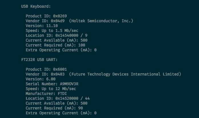
Output on Mac
On Windows, there are more hoops you’ll need to do to get the VID and PID. So I think it’s better just to skip and trust my value.
Code Them Up
We’ll be using for this one. The reason was because this is the language used for creating firmware and also the easiest to get started after libftdi is installed.
We’ll be using C as our language of choice. We also assume we’re using somekind of Unix or Unix-like environments such as macOS or Linux. This code will not compile on Windows as it has no usleep function.
Here’s a fully-commented code, and we save it as blinky.c .
/* These are standard headers used in Unix systems */

#include <stdio.h>
#include <unistd.h>
#include <ftdi.h>

#define LED 0x08  /* CTS PIN */

int main()  {
    unsigned char c = 0;
    /* ctx is the FTDI context, we'll use this to control the
     * FTDI devices later. We'd need to initialise it first
     */
    struct ftdi_context ctx;
    ftdi_init(&ctx);
    /*  Open FTDI Devices based on FTDI VID/PID */

    if(ftdi_usb_open(&ctx, 0x0403, 0x6001) < 0) {
        puts("Can't open device");
        return 1;
    }

    /* Enable bitbang mode with a single output line */
    ftdi_set_bitmode(&ctx, LED, BITMODE_BITBANG);

    /* Endless loop: invert LED state,
     * write output, pause 1 second */
    for(;;) {
        c ^= LED; /* C = C XOR C which will flip the bits*/
        ftdi_write_data(&ctx, &c, 1);
        usleep(200000); /* pause for 200000 microseconds*/
    }
}
Let’s compile them using gcc . We assume that you have libftdi on standard path.
$ gcc blinky.c -o blinky -lftdi
This will output executable named blinky in the same folder. If your ftdi
libraries and headers are in different directories you’d need to change the
command slightly by add ngi -I and -L . For example, when you’re using
Macports the library will be installed in /opt/local/include/libftdi1 and
/opt/local/lib for the headers and library respectively. Therefore the
command will be
gcc blinky.c -o blinky -I/opt/local/include/libftdi1 \
  -L/opt/local/lib -lftdi1`
And then we’d need to execute it using ./blinky . And here’s blinky in its full glory:
Blinky in its full glory GIF
Conclusion
FTDI is very convenient piece of hardware. By utilising its capability of writing and reading from a digital signal pin to do bit-banging, we’re able to test sensors by emulating its peripheral communication such as SPI, UART, and I²C without cross compiling.
Happy Hacking!